UA1775
77.5 mm
56 mm
100 - 400 mm
90 - 340 mm
Stegbauarten
UA1775.020
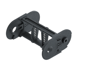
Geschlossener Rahmen
- Gewichtsoptimierter, geschlossener Kunststoffrahmen mit besonders hoher Torsionssteifigkeit.
- Außen/Innen: Nicht zu öffnen.
UA1775.030
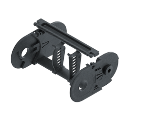
Rahmen mit außen aufklappbaren und lösbaren Stegen
- Gewichtsoptimierter Kunststoffrahmen mit besonders hoher Torsionssteifigkeit.
- Außen: Aufklappbar und lösbar.
UA1775.040
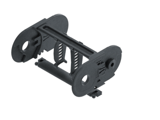
Rahmen mit innen lösbaren Stegen
- Gewichtsoptimierter Kunststoffrahmen mit besonders hoher Torsionssteifigkeit.
- Innen: Aufklappbar und lösbar.
Einbaumaße
Freitragende Anordnung

| KR [mm] | H [mm] | Hz [mm] | LB [mm] | UB [mm] |
|---|---|---|---|---|
| 90 | 257 | 297 | 438 | 206 |
| 115 | 307 | 347 | 516 | 231 |
| 140 | 357 | 397 | 595 | 256 |
| 165 | 407 | 447 | 673 | 281 |
| 190 | 457 | 497 | 752 | 306 |
| 240 | 557 | 597 | 909 | 356 |
| 285 | 647 | 687 | 1050 | 401 |
| 340 | 757 | 797 | 1223 | 456 |
Belastungsdiagramm für freitragende Länge
in Abhängigkeit von der Zusatzlast.
Bei längeren Verfahrwegen ist ein Durchhang der Energieführung je nach Einsatzfall technisch zulässig.
Ketteneigengewicht qk = 3,03 kg/m bei Bi 150 mm. Bei abweichender Innenbreite verändert sich die maximale Zusatzlast.

Geschwindigkeit
bis 10 m/s

Beschleunigung
bis 35 m/s2

Verfahrweg
bis 6,8 m

Zusatzlast
bis 25 kg/m

Gleitende Anordnung
GO Modul mit gleit-optimierten Kettengliedern

| KR [mm] | H [mm] | GO-Modul RKR [mm] | LB [mm] | UB [mm] |
|---|---|---|---|---|
| 90 | 231 | 400 | 1313 | 643 |
| 115 | 231 | 400 | 1440 | 688 |
| 140 | 231 | 400 | 1575 | 733 |
| 165 | 231 | 400 | 1715 | 779 |
| 190 | 231 | 400 | 1868 | 828 |
| 240 | 231 | 400 | 2225 | 951 |
| 285 | 231 | 400 | 2580 | 1081 |
| 340 | 231 | 400 | 3015 | 1240 |
Geschwindigkeit
bis 3 m/s
Beschleunigung
bis 8 m/s2
Verfahrweg
bis 200 m
Zusatzlast
bis 25 kg/m

Die gleitende Energieführung muss in einem Kanal geführt werden.
Das am Mitnehmer montierte GO-Modul ist eine definierte Abfolge von 5 angepassten KR/RKR-Kettenlaschen.
Für eine gleitende Anwendung ist die Verwendung von Gleitschuhen erforderlich.