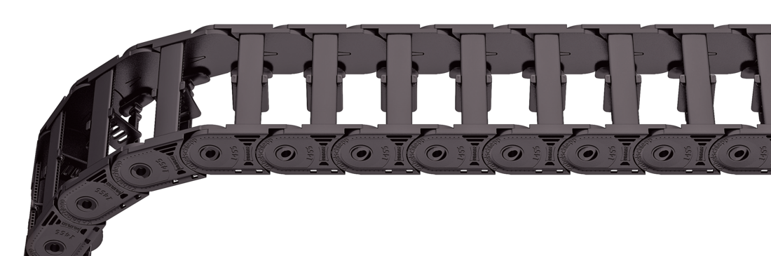
Stay variant 040 – with lamellae in the inner radius
Właściwości
Weight-optimised plastic frame with particularly high torsional rigidity.
Lamellae can be swivelled at any position on one side
Inside: swivelling.
Układ na każdym ogniwie
Bi
25 - 78
mm
Wymiary
Wymiary
The maximum cable diameter strongly depends on the bending radius and the desired cable type. Please contact us.
Design 040 is not suitable for gliding arrangements.
Obliczanie długości prowadnika kablowego
Cable carrier length Lk: Lk ≈ LS/2 + LB
Cable carrier length Lk rounded to pitch t
<table class="table">
<thead>
<tr>
<!-- Reihenfolge gemäß Kundenwunsch -->
<th class="t"><strong>t</strong><br>[mm]</th>
<th class="hi red"><strong>h<sub>i</sub></strong><br>[mm]</th>
<th class="hg"><strong>h<sub>G</sub></strong><br>[mm]</th>
<!-- Bi Spalte nur anzeigen wenn einzelner Wert oder Range -->
<!-- Bk und BEF für alle Ketten -->
<th class="bk"><strong>B<sub>k</sub></strong><br>[mm]</th>
<!-- KR Spalte nur anzeigen wenn einzelner Wert oder Range -->
<th class="qk"><strong>q<sub>k</sub></strong><br>[kg/m]</th>
</tr>
</thead>
<tbody>
<tr>
<!-- Reihenfolge gemäß Kundenwunsch -->
<td class="t">45.5</td>
<td class="hi red">25</td>
<td class="hg">36</td>
<!-- Bi Spalte nur anzeigen wenn einzelner Wert oder Range -->
<!-- Bk und BEF für alle Ketten -->
<td class="bk">Bi + 16</td>
<!-- KR Spalte nur anzeigen wenn einzelner Wert oder Range -->
<td class="qk">0.65 – 0.80</td>
</tr>
</tbody>
</table>
Bi [mm]
25
38
58
78
KR [mm]
52
65
95
125
150
180
200
Przykład zamówienia
ET1455
Typ
•
040
Wariant poprzeczki
•
78
B [mm]
•
150
KR [mm]
-
1456
Lk [mm]
VS
Układ poprzeczek
Złączki końcowe
Złączki końcowe
Recommended tightening torque: 6 Nm for screws M6 - 8.8
Bi [mm]
nz
25
2 x 2
38
2 x 3
58
2 x 4
78
2 x 6
The end connectors are optionally also available without strain relief comb. Please state when ordering.
Connection point F – fixed point M– driver
Connection type A – threaded joint outside (standard) I – threaded joint inside H – threaded joint, rotated 90° to the outside K – threaded joint, rotated 90° to the inside